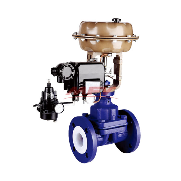
Pneumatic lined diaphragm valve

Pneumatic lined diaphragm valve
Nominal diameter: DN15 ~ 300mm
Nominal pressure: PN0.6 ~ 2.5MPa
Main material: Gray cast iron, low carbon stainless steel, carbon steel, stainless steel
Drive: electric, pneumatic, manual
Design and manufacture: BS5156
Length of the structure : BS5156
Flange connection size: BS4504, DIN2532, JIS B2212, ANSI B16.1, ISO2004
First, the pneumatic valve lined diaphragm overview
Pneumatic diaphragm valve lined by the diaphragm valve and pneumatic actuator composed of two parts, it is compressed air as a driving force, the actual flow of the medium in the process of regulating the flow of media. Pneumatic fluorine fluorine diaphragm valve due to the structure of the valve with a corrosion-resistant liner and corrosion-resistant diaphragm, no stuffing box structure, the throttle element is flexible diaphragm, valve body smooth, so the pneumatic diaphragm diaphragm valve has a negative force Small, high flow, no leakage and convenient and reliable, fire and explosion-proof advantages, pneumatic valve lined with fluorine diaphragm valve widely used in industrial automation systems of strong acid, alkali, strong corrosion, high viscosity, with grain, with fiber and toxic and Not allow pollution of the media flow regulation.
Second, pneumatic lining fluorine membrane valve main parts and materials
| Serial number | Part Name | grey cast iron | Carbon steel | stainless steel | Ultra-low carbon stainless steel | ||
| Z | C | P | R | PL | RL | ||
| 1 | Body, bonnet, disc | HT250 | WCB | CF8 | CF8M | CF3 | CF3M |
| 2 | Valve stem | 35 | 1Cr13 | 1Cr18Ni9 | 1Cr18Ni12Mo2Ti | 00Cr18Ni10 | 00Cr17Ni14Mo2 |
| 3 | Lining layer | FEPF46, PFA (soluble polytetrafluoroethylene), PCTFE (F3), PO (polyolefin) | |||||
| 4 | Diaphragm | FEPF46, PFA (soluble polytetrafluoroethylene), CR (neoprene), EPDM (ethylene propylene rubber) | |||||
| 5 | Stem nut | ZcuAl10Fe3 | |||||
| 6 | bolt | 35 | 35 | 1Cr17Ni2 | 1Cr17Ni2 | 1Cr17Ni2 | 1Cr17Ni9Ti |
| 7 | Nut | 45 | 45 | 0Cr18Ni9 | 0Cr18Ni9 | 0Cr18Ni9 | 0Cr18Ni9 |
Third, pneumatic lining fluorine diaphragm valve technical parameters
| Nominal diameter DN (mm) | 15 | 20 | 25 | 32 | 40 | 50 | 65 | 80 | 100 | 125 | 150 | 200 | 250 | |
| Rated flow coefficient Kv | 8 | 12 | 16 | 28 | 60 | 68 | 90 | 160 | 300 | 410 | 618 | 1200 | 2150 | |
| Flow characteristics | Approximate quick opening characteristics | |||||||||||||
| Nominal pressure PN (MPa) | 0.6, 1.0, 1.6, 2.5 | |||||||||||||
| Connection Type | Flange connection: PN1.0 according to JB78 standard | |||||||||||||
| Equipped with actuator model | ZHA, ZHB | |||||||||||||
| Effective area Fece2 | 280 | 400 | 600 | 1000 | ||||||||||
| Travel Lmm | 8 | 10 | 16 | 25 | 40 | 60 | ||||||||
| Mode of action | Qi off; open air | |||||||||||||
| Spring pressure range (KPa) | Standard 20-100, optional 40-200,20-60,60-100 | |||||||||||||
| Supply pressure (MPa) | Standard 0.14 optional 0.24 | |||||||||||||
| Air source connector | M16 × 1.5 | |||||||||||||
| Inherent adjustable R | 30: 1 | |||||||||||||
| Operating temperature | -30 ~ + 150 ℃ | |||||||||||||
Fourth, pneumatic lined diaphragm valve main dimensions
standard value | ||||||||||||||
DN (mm) | NPS (inch) | L | D | D1 | D2 | f | b | Z-фd | d0 | H | H1 | WT (kg) | ||
15 | 1/2 | 125 | 95 | 65 | 45 | 2 | 14 | 4-ф14 | 100 | 105 | 110 | 3.5 | ||
20 | 3/4 | 135 | 105 | 75 | 55 | 2 | 16 | 4-ф14 | 100 | 115 | 125 | 4 | ||
25 | 1 | 145 | 115 | 85 | 65 | 2 | 16 | 4-ф14 | 120 | 120 | 135 | 5.5 | ||
32 | 11/4 | 160 | 135 | 100 | 78 | 2 | 18 | 4-ф18 | 120 | 125 | 150 | 8 | ||
40 | 11/2 | 180 | 145 | 110 | 85 | 3 | 18 | 4-ф18 | 140 | 135 | 175 | 11 | ||
50 | 2 | 210 | 160 | 125 | 100 | 3 | 20 | 4-ф18 | 140 | 155 | 195 | 14 | ||
65 | 21/2 | 250 | 180 | 145 | 120 | 3 | 20 | 4-ф18 | 200 | 170 | 200 | 23 | ||
80 | 3 | 300 | 195 | 160 | 135 | 3 | 21 | 4-ф18 | 200 | 200 | 255 | 29 | ||
100 | 4 | 350 | 215 | 180 | 155 | 3 | 21 | 8-ф18 | 280 | 270 | 325 | 46 | ||
125 | 5 | 400 | 245 | 210 | 185 | 3 | 24 | 8-ф18 | 320 | 335 | 405 | 70 | ||
150 | 6 | 460 | 280 | 240 | 210 | 3 | 24 | 8-ф23 | 320 | 370 | 450 | 95 | ||
200 | 8 | 570 | 335 | 295 | 265 | 3 | 26 | 8-ф23 | 400 | 480 | 600 | 170 | ||
250 | 10 | 680 | 390 | 350 | 320 | 3 | 28 | 12-ф23 | 500 | 545 | 620 | 270 | ||
300 | 12 | 790 | 435 | 395 | 362 | 4 | 24 | 12-ф23 | 500 | 585 | 680 | 320 | ||


